Introduction
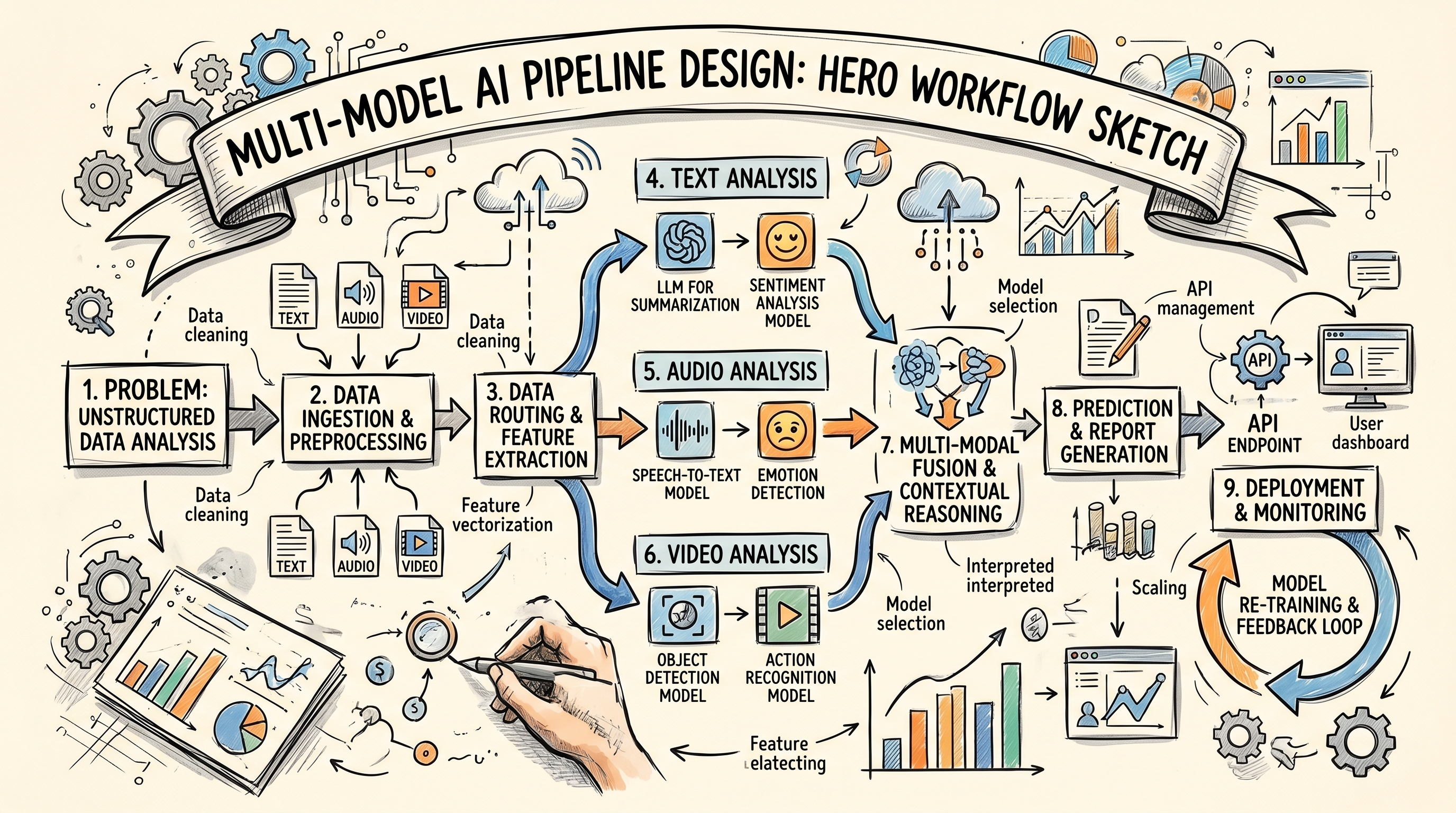
Designing a multi model AI pipeline is the practice of breaking a production task into its constituent AI operations, selecting the right model for each operation, and wiring them together into a workflow that produces finished output from a defined input. The discipline is more architectural than technical. A well designed pipeline is legible, testable, and modifiable. A poorly designed pipeline works once and breaks when anything changes.
This guide walks through the four phase design process used to build production pipelines at scale. It covers problem decomposition, node selection, wiring logic, and validation. The target reader is a creative lead, production engineer, or workflow designer who is building their first serious pipeline and wants a systematic approach rather than trial and error.
Phase one: problem decomposition
The first phase is decomposing the production task into AI operations. This step is the single most important part of the process and the most commonly skipped. Teams often jump directly to node selection without first understanding the structure of the problem. The result is a pipeline that works but does more than needed, or misses steps that become problems later.
The decomposition method that works reliably is to describe the task in plain language as a sequence of actions. For a UGC ad the sequence might be: generate an image of a creator, animate the creator into a short video matching a script, generate voice for the script, assemble video and voice with captions. Each of these is one step. Each step is one or more AI operations. The language should avoid naming tools or models because the model selection comes later.
A good decomposition produces a list of five to fifteen steps for a typical production task. Fewer than five and the decomposition is probably too coarse. More than fifteen and it is probably too fine. The sweet spot is steps that are small enough to map to specific AI operations but large enough that each represents real work.
The decomposition should also identify inputs and outputs explicitly. What does the pipeline need from the user to start. What does the pipeline produce as its final deliverable. What intermediate outputs need to be captured for review or reuse. These questions often surface ambiguities in the original task that would otherwise become problems during implementation.
Phase two: identifying node boundaries
The second phase maps the decomposed steps to nodes. Most steps map to a single node but some steps require multiple nodes or benefit from being split. A step like generate an image of a creator might be one image generation node in simple cases, but for a production pipeline where character consistency matters, it might decompose further into a character design step using a CHAT node, an image generation step, and a reference caching step.
The heuristic for node boundaries is that each node should do one clearly defined thing. Image generation is one thing. Voice synthesis is another. Assembly is a third. Nodes that try to do more than one thing become difficult to test and reason about. Nodes that do less than a complete operation force downstream nodes to do cleanup that does not belong to them.
Some steps are handled by utility nodes that do not generate new content but transform data between steps. A CHAT node that takes a brief and produces a structured prompt for downstream generation is a utility node. A JSON_EXTRACTOR that parses a CHAT output into fields that multiple downstream nodes consume is a utility node. These nodes are essential for making pipelines modular but are often missed by designers thinking only about generation steps.
By the end of phase two the designer has a list of nodes corresponding to steps, with each node's purpose defined and the utility nodes identified that bridge between generation steps. This list is the skeleton of the pipeline.
Phase three: node selection
The third phase selects the specific model or execution mode for each node. This is where knowledge of the AI model landscape matters. For each node the designer picks which model will run the operation based on output quality, speed, cost, and compatibility with surrounding nodes. A video generation node might select Veo 3.1 Fast for dialog heavy content or Kling 2.0 for action heavy content.
The selection should be informed by testing rather than assumption. Teams that pick models based on which one is currently in fashion often end up with pipelines that produce inconsistent output because the chosen model is not actually the best fit for the specific task. A small test batch before committing to a model in a pipeline saves significant rework later.
Cost and speed matter alongside quality. A model that produces ten percent better output at three times the cost is usually the wrong choice for production because the cost scales with volume. A model that produces slightly worse output at half the cost often wins in production even when it would lose on a quality only comparison. The right framing is quality per dollar rather than absolute quality.
By the end of phase three the designer has a complete node list with each node mapped to a specific model, execution mode, and parameter set. The pipeline is now concrete enough to build in the canvas.
Phase four: wiring and validation
The fourth phase is building the pipeline in the canvas and wiring the edges that carry data between nodes. The wiring needs to match the input and output fields of each node. An image generation node outputs an image. A video generation node that needs a reference image accepts that image. The edge connects the two. Wiring errors are the most common source of pipeline failures, so careful attention here pays off.
Validation happens throughout the wiring process and after the pipeline is complete. The pipeline should be tested end to end with representative inputs. Every possible input variation should be tested, especially edge cases like empty fields, very long inputs, or unusual combinations. The goal is to surface failure modes while the pipeline is still easy to modify rather than after it has been deployed to team use.
A good validation pass includes reviewing the output quality at each node, not just the final output. If the final output is poor, the validation should identify which node is contributing the problem. If the output is good, the validation should confirm that the pipeline behaves correctly under variation rather than only for a happy path input.
The pipeline is ready for production use when it produces consistent quality output across a range of representative inputs, when failure modes are known and handled, and when the operator time to run the pipeline is reasonable for the output value. Until these conditions are met the pipeline should stay in refinement rather than being released to team use.
Real example: a podcast video pipeline
A concrete example makes the process clearer. Consider a pipeline that produces a podcast video from a script. The decomposition might produce these steps: generate a reference image of the podcast host, animate the host speaking the script with lipsync, generate the voice of the host delivering the script, merge the video and voice, add a podcast studio background element, and add captions and title card.
The node mapping produces an image generation node for the host, a VIDEO_LIPSYNC node for the speaking animation, a TEXT_TO_SPEECH node for the voice, a VIDEO_AUDIO_MERGE node for the combination, a compositing node for the background, and an assembly node for captions and title. Eight nodes total including one CHAT node at the top to structure the script into the right format for downstream use.
Model selection picks Flux for the host image, Veo for the lipsync video, ElevenLabs for the voice, and internal Vertex nodes for the merge and compositing steps. Wiring connects each output to the appropriate downstream input. Validation tests the pipeline with three sample scripts of different lengths and styles. The validated pipeline is saved as a template and becomes reusable for all future podcast video production.
Common design mistakes
The most common design mistake is skipping decomposition and jumping straight to node assembly. This produces pipelines that work for the first test case and break when the second test case has slightly different characteristics. The decomposition phase surfaces assumptions early and catches them when they are cheap to fix.
The second common mistake is using too many nodes. A node count of fifty suggests that many operations are probably redundant or could be consolidated. Canvas workflows become difficult to reason about above fifteen to twenty nodes. Decomposing at the right granularity prevents this problem.
The third common mistake is not planning for variation. A pipeline designed for one specific input often fails when the team tries to reuse it for related inputs because the design baked in assumptions specific to the original case. Designing for the variation space of realistic inputs from the start makes the pipeline more reusable.
FAQ
How long does it take to design a first pipeline?
A first pipeline for a meaningful production task typically takes three to five hours of design time including decomposition, node selection, building, and validation. Subsequent pipelines are faster because the team has learned the patterns and has a template library to build on.
Should I design pipelines alone or with the team?
Early design work benefits from being done by one or two people who understand the task deeply. Validation benefits from involving team members who will use the pipeline. A mixed approach of solo design and team validation works well for most teams.
How do I know when a pipeline is too complex?
The pipeline is too complex when a team member other than the designer cannot follow its structure by looking at the canvas. A pipeline that needs significant explanation to understand is usually over engineered and benefits from being simplified or decomposed into smaller pipelines that call each other.